In this article
Planning Engine Management and Input Demands
Selecting an aftermarket electronic control unit requires defining your racing goals, target engine power, and budget before purchasing hardware. High-output engines generate complex operating demands that typically call for more sensors to support data acquisition, tuning, and potential troubleshooting. Tuners recommend choosing an engine management system that either you or your designated tuner has practical experience operating.
Planning for future sensor additions is helpful when selecting an ECU. Running out of inputs or outputs can limit what data you can log or what you can control, which could impact vehicle performance. When builders deviate from a plan or rush vehicle assembly, problems and overlooked wiring details can easily arise.
Pre-Terminated Versus Custom Harness Construction
Depending on the application, builders might have the option to install a pre-terminated harness, or construct a custom harness if they want full control and possess the necessary skills. Pre-terminated options offer plug-and-play convenience with factory sensor connectors and sufficient overall length for flexible ECU mounting. Modifying a pre-terminated loom helps less experienced builders avoid complex diagnosis issues.
Experienced builders often construct custom harnesses from unterminated wire bundles to tuck wiring seamlessly and integrate additional sensors into one main engine loom. Certain applications may need a sealed harness using molded boots and fluid-resistant DR-25 heat shrink sleeving. In methanol applications, this construction may be desirable because it is generally more resistant to abrasion, heat, and aggressive chemicals.
Hybrid Wiring Methods and Assembly Tools
A hybrid assembly method represents a common choice for project builds. Builders start with a pre-terminated engine harness, modifying routing as needed, and run additional sensor circuits alongside the existing loom. Project vehicles often use dedicated sub-harnesses for main power, injectors, ignition coils, and extra inputs and outputs to support secondary components.
Reliable wiring assembly requires proper hand tools and high-quality materials. A quality pair of wire strippers prevents fatigue when building numerous connectors from scratch, replacing basic squeeze-and-yank tools. Specialty plugs such as Deutsch connectors require designated crimpers for each connector type. It is also a good idea to have a hydraulic crimping tool on hand for battery lugs and cable terminals.
Related posts

Engines & Power Units
Formula 1 and Road Relevance: Why the Hybrid Power Unit Created a Conflict
Engines & Power Units
BMW N52 Racing Engine Guide: Club Competition Swap and Endurance Tuning
Baseline Sensors for Engine Operation
A basic electronic fuel injection installation relies on critical sensors to run properly. Manifold absolute pressure, intake air temperature, and coolant temperature sensors track intake charge and thermal status. A throttle-position sensor monitors throttle angle, while crank and camshaft position sensors supply the essential timing signals required for sequential fuel injection.
Exhaust monitoring requires a wideband oxygen sensor, while dedicated fluid sensors monitor system operation. A fuel-pressure sensor is very important because it verifies that the fuel system maintains proper fuel pressure for the engine and fuel injection setup. Lubrication monitoring relies on an oil-pressure sensor, which helps builders tell whether the engine is healthy.
Forced Induction and Engine Protection Sensors
Turbocharged and high-horsepower combinations require specialized sensors for boost management and engine protection. A wastegate dome-pressure sensor provides consistent pneumatic boost regulation on high-output packages. Measuring exhaust backpressure assists turbocharger efficiency evaluations and informs air-fuel tuning choices across varied racing environments.
Exhaust gas temperature sensors aid engine tuning and cylinder troubleshooting, highlighting potential injector or ignition faults if one cylinder strays from the others. For high-horsepower water-jacketed engines, a coolant-pressure sensor is almost a must-have item. If a cylinder head lifts or a head gasket pushes, pressurizing the cooling system beyond normal levels, the ECU can depower the car.
Drivetrain Monitoring and Power Management
Behind the engine, builders install transmission temperature, transmission pressure, and torque converter pressure sensors. These instruments are used to monitor the operational health of drivetrain components and provide diagnostic data that helps racers adjust their tune based on prevailing track conditions.
A basic g-meter is another sensor builders can implement in a serious drag racing build, providing data that assists with tuning. Beyond a basic two-axis g-meter, Alford explains that Davis Technologies systems like the Profiler or VPS are widely used by front-running racers for traction-control and power-management strategies, though they can fall outside some budgets.
Ignition Coil Driver Configurations
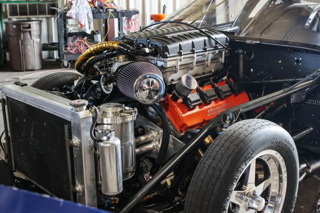
Wiring considerations vary across engine platforms due to harness length, sensor locations, and ignition architecture. Where sensors sit differs by engine design, meaning builders constructing a custom harness must account for required wire length. Factory General Motors LS engines feature what are called smart coils, which can be directly triggered by the electronic control unit.
In contrast, OEM Gen-III Hemi and Coyote engines utilize what are commonly called dumb coils. These setups require an ignition-coil driver module installed between the control unit and the ignition coils. The ECU triggers the driver module, which can then fire each coil.
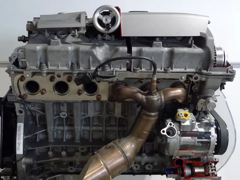
Related technical guide: BMW N52 Racing Engine Guide: Club Competition Swap and Endurance Tuning.
Sources: ECU Wiring Basics For Race Car EFI Systems Explained.